|
|
Industrial soldering
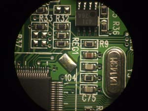
Surface-mount technology (SMT) is a design standard for constructing electronic circuits where the components are mounted directly onto the surface of the circuit board. Surface mount technology is applied in electronics manufacturing of highly-populated circuit board with very fine and closely-spaced copper conductors and pads. SMT boards are built on an automated assembly line which results in lower production costs and better product reliability. SMT process is little more complex than thru-hole technology but offers better reliability and electrical conductivity.
Advantages of SMT over standard through-hole technology are:
- Components can be soldered on both sides of circuit board
- Improved shock and vibration resistance as a result of the lower mass of components
- Faster component replacement in repair
- Reduction in size and weight of circuit board, and cost reduction as well
- Electrical noise reduction
- Boards contain fewer layers and almost no through holes
 |
SMT components are inside the same as through-hole components but they are mechanically redesigned to have small metal tabs or end caps that could be directly soldered to the surface of the printed circuit board. SMT component leads are surface-soldered to both sides of circuit board (on the top and bottom sides of circuit board), rather than inserted into plated-through holes and wave-soldered.
BGA or Ball Grid Array is also a kind of SMD with no leads or legs at all. These special electronic components have tiny metallic spots underneath the components. They are soldered on the PCB using solder balls. |
Three basic steps in manufacturing of SMT assemblies are:
- A stencil is placed over the board. Stencil is a metal mask used in place of a screen and it is normally used for thicker paste deposits. This stencil allows solder paste to pass through the pads on circuit board while blocking paste from all other areas. Solder paste is made from powered tin and lead, flux, and binders. The solder paste remains tacky after application and holds components in place until solder can be reflowed.
- With robotic hand or other automated machine components are picked and placed onto pasted board. SMT components are fed into the machine on reels of plastic tape. Each component is located in separate pocket on tape and held in position by clear cover tape. As it approaches the machine pickup head the cover tape is peeled back to expose the component. The pickup head is a vacuum nozzle with centering jaws that pick the component from its tape pocket. This pickup head is guided by a camera. It moves to the proper board location and lowers the component onto pads.
- All components should be placed on board before the board is moved to next step - vapor phase reflow soldering machine. The board is preheated to 210 degrees Fahrenheit to prevent thermal shock from damaging components. This temperature is high enough to drive off paste solvents from the board. Then the board is passed through a chamber of vaporized fluorocarbon heated at 420 degrees Fahrenheit. The hot fluorocarbon condenses on the printed board assembly and heats solder to the melting point, soldering components to their pads. If a component has been placed slightly off center it will tend to self align due to the surface tension of the solder. At the end of process, the printed board assembly is cleaned with a solvent to remove remains of flux.
|


